
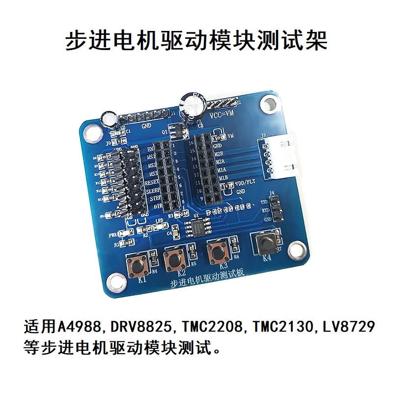
This test frame is suitable for stepper motor drive modules commonly used in the market: A4988, DRV8825, TMC2208, TMC2100, TMC2130, LV8729, etc. The drive module needs to be purchased separately without delivery.
Instructions for use:
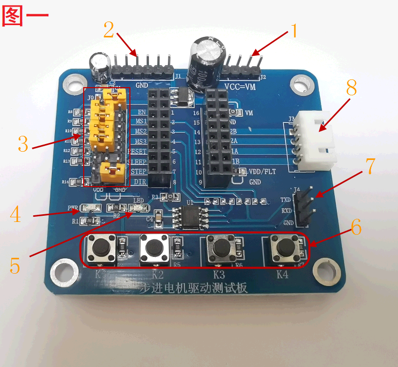
Description of Figure 1:
1. VCC: Connect to an external power supply to supply power to the board and stepper motor, and supply power according to the operating voltage of the stepper motor.
2. GND: Connect to the power ground.
3. Configure the port: when the jumper is not added, the EN pin is pulled down to ground by default, and other ports are pulled up to 5V by default. Can be configured to connect to VDD or GND according to the jumper.
4. VDD power indicator light, when power on, it means that VDD=5V has output.
5. Work indicator, always on means that the single-chip microcomputer outputs pulses with 50% duty cycle of PWM to the pin; the single-chip microcomputer is connected to the STEP port through the R3 resistor by default. If you want to provide PWM pulse externally, you can remove the R3 resistor and then connect the external PWM pulse.
6. Motor speed adjustment buttons: K1: Long press the frequency to continuously slow down, K2: Long press the frequency to continuously increase, K3: Press once to slow down the frequency, K4: Press once to make the frequency faster. K1 K2 is equivalent to speed continuous adjustment, K3 K4 is equivalent to speed fine adjustment. Restore the default frequency after power failure.
7. The MCU program update port. If you want to write a program to control the motor, you can update to the MCU through this port. But no technical support is provided.
8. Stepper motor interface: connect to stepper motor.

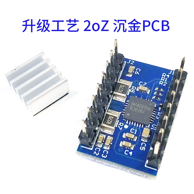
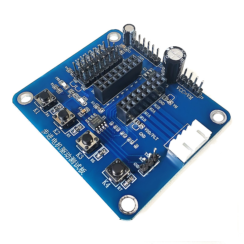
Description of Figure 2
1. The stepper motor drive module VDD is powered, and it is connected to the 5V of the board through a 0R resistor.
2. The stepper motor drive module VM is powered and connected to the VCC power supply through a 0R resistor.

Description of 3
1. The EN pin pull-down resistor is enabled by default, and the jumper cap connected to the VDD module does not work.
2, 3, 4, subdivided pin pull-up resistor, the default is connected to the pull-up to VDD. Set the subdivision according to different motor drive modules. Some modules have only two subdivision pins, only two need to be configured, and the other one does not care about it.
5. The RESET pin pulls up the resistor, and the module does not work when the jumper is connected to GND. Some modules don't have this pin, don't care about it.
6. SLEEP pin pull-up resistor, the module does not work when the jumper is connected to GND. Some modules don't have this pin, don't care about it. Note: The SLEEP and RESET pins of some modules are connected, and only one pin needs to be configured.
7. DIR pin pull-up resistor, forward and reverse settings, jumper cap not connected or connected to VDD reverse, jumper grounded and forward.